Nowadays, in most electrical appliances such as audio and video appliances, various types of chargers, computer power supplies and inverters, switching circuits are used for voltage and current converters. The reason is that depending on the linear power supply, which perform the voltage and current converter with the help of large transformers, they are light in weight and naturally require less capacity. Based on this, it can be said that their rates are lower and affordable compared to other power sources.
The most important feature of these circuits is their high efficiency, note that a wider input electrical pressure can be applied to this Printed circuits input but their output are completely fixed without using high energy consumption regulators. A linear source creates a one-way output by losing power, but in the switching method, the duration of the switch, voltage and output current are adjusted by innovation. If there is a proper planning to use this method, it can be said that almost 90% of the results will be achieved. The most famous and desirable example for such power sources are mobile chargers.
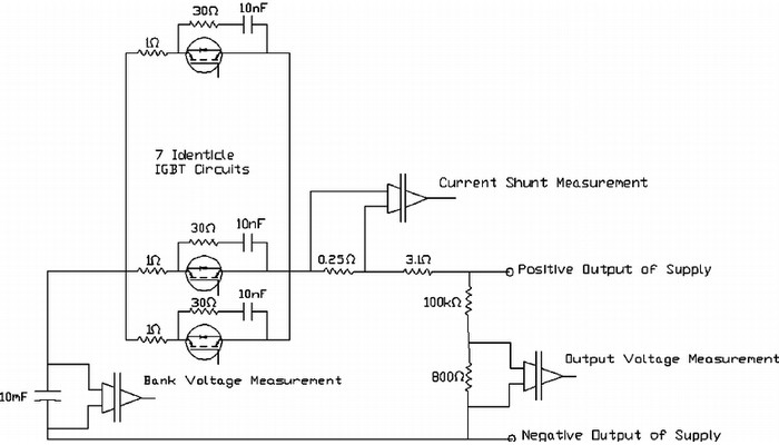
How switching circuits work
Maybe there is a question for you, how does a switching power supply work?
In theory, teaching how this resource works is not so complicated. Think of this resource as a black box with only its input and output terminals available to you. Under these conditions, a switching circuit behaves exactly like a linear power supply. The biggest difference between them is the continuous regulation of the load circulation which is obtained from the input circulation to maintain the load voltage.
The other example, though, does the same thing by switching the input voltage off and on, and then by blocking the average current applied by changing the pulse width. When more output circulation is desired through the load, this is done by increasing the duration of the pulses being on.
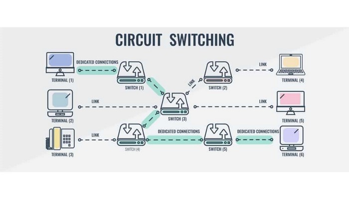
Effective factors in the burning of the oscillator IC in the source of the switching power supply
The most important part of any switching circuit is its vibrating part. Transistor, few capacitors and resistance are simple parts that are used in this part. Of course, newer and larger models also have IC components. In such a way that even strong transistors can be identified in an IC to separate from the circuit that produces the vibration.
The role of the vibration generating part in this power supply is unlike adapters that use metal core transformers and linear regulators to operate at minimum frequency and cause a lot of energy wastage. If the movement of the key transistors is activated at a special frequency and the bandwidth is organized, less energy is wasted.
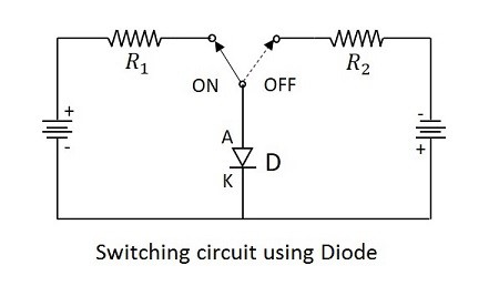
Factors influencing the burning of the switching power supply oscillator IC
The first factor in the burning of the oscillator IC is the poor quality of its model.
Another reason that we can mention for this is the failure of the diode or regulator to stabilize the input voltage of this part. This also happens if the parts of the input part of the power supply are defective.
Among other factors of oscillator IC burning, we can mention the vibrations of the channel's power input.
Line continuity
pbc, printed circuit board In the input section, which occurs due to excessive heat in the circuit, this is one of the other factors.
Switching power supply
In the current situation, the switching power supply is mostly used in home televisions, mobile phones, computer systems, power amplifiers, DC motors, etc. The design of this power supply is such that it uses switching methods in the semi-conductor base to create the appropriate output voltage. In its design, a basic power supply conversion, power and a restraint circuit are used. The most important feature of this power source is its higher efficiency compared to linear power sources.
The most important reason for creating high efficiency in this system is a type of transistor that switches between two states of connection and disconnection and prevents and limits the wastage of high energy power. When the transistor of this source is fully connected and transfers the current, its voltage drop will be as low as possible. When this source is completely cut off, current cannot pass through it. In this situation, the transistor acts like a proper switch.
In the end, unlike the linear power supply that performs voltage control in the form of a reducer, this type of switching power supply can be one of the three modes of reducing Buck, increasing Boost, or inverting the input voltage of Buck Boost polarity. The circuits we mentioned mainly form the bases of the power supply. Of course, these three circuits have one difference, which is the location of the output inductor and capacitor in the circuit.
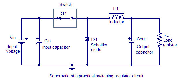
Types of switching circuits
The switching power supply is distributed in two comprehensive categories, forward and flyback. Despite the many similarities between these two types of food sources, they also have unique characteristics that distinguish them from each other. The mode of operation and the placement of the magnetic material indicates the type of circuit.
Forward switching circuit
The power switch
is a powerful IGBT, MOSFET transistor whose on and off frequency must be much higher than the operating frequency of the circuit.
Inducer
is an energy storage material and its function is very similar to piston and flywheel. However, the possibility of a transformer instead of an inductor is felt due to the change in the amount of electrical pressure and the production of insulation.
Capacitor
The capacitor is usually an energy storage material to keep the output voltage at its specified value and not have a lot of ripple.
The rectifier
is usually a super fast diode that uses a Schottky diode and should definitely have a very low on/off time.
How the circuit works
In the same way that the piston has no power and the power is created by the flywheel and in the next period the piston gives power to the flywheel. Here too, when the switch is open, the power is created by the inductor with full circulation from the diode side, and in the next cycle, by closing the key, the inductor gains power through the input source.
Flyback switching circuit
By connecting the power switch, the inductor gets energy with the help of the source, and in this state the diode turns off. By cutting off the switch, the load flow continues through the diode, the inductor and the supply.
If you have any questions regarding the order of the printed circuit board ( PCB iran ), contact Arya Madar Arjomand.